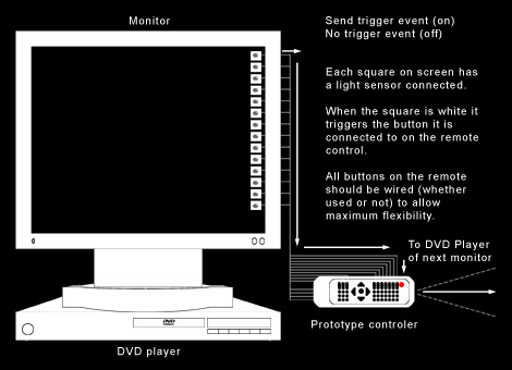
The device and how it all works.
The Video Networks #1 interface system employs a combination of reverse engineered inexpensive consumer electronics and some custom hardware to enable devices such as DVD players, monitors, video cameras, projectors etc. to in effect see each other, network, communicate and influence each other.
The device consists of two battery compartments, one reverse engineered universal remote control, a custom made switch simulator (the board) and ten light sensors. The light sensors, binary triggers (0/1), are attached to a light emitting sourse such as a monitor which are triggered when the part of the monitor under the sensor is sufficently bright. When triggered the sensor activates a button on the universal remote control via a switch simulator, which has replaced the controls physical buttons, in effect replacing the need for a user. These buttons can be programmed to trigger any function on any infra-red receiving device to control its behaviour.
Diagram 2: Example video network node. This system allows the possibility for almost countless devices counted in many different configurations (restricted only by space and layout). Example shown is used in Video Network #1: Dialogues. Arrows indicate flow of interaction.
